Collection: Solis inverters – Efficient energy conversion

Smart battery advice

Which home battery suits your Solis hybrid inverter?

Calculate the recommended battery capacity based on your consumption, solar panels and energy tariff — and automatically discover compatible home batteries for your Solis inverter from the current Rebor range.

Start the battery calculator →

Solis inverters provide efficient conversion of solar energy into stable grid power. With conversion efficiencies up to 98% and advanced hybrid technology, these systems are widely used in both residential and commercial PV installations worldwide.

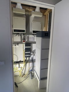
Solar installers, energy consultants and PV professionals rely on Solis S6 hybrid inverters for reliable energy conversion, broad battery compatibility and intelligent management of energy flows within modern solar energy systems. Combine your Solis inverter with a compatible home battery from Pylontech, BYD or Dyness for maximum energy independence.

In summary: A Solis inverter converts solar energy into usable power while simultaneously managing battery storage, self-consumption and grid interaction via advanced algorithms such as Solis AI — the intelligent energy management system that automatically responds to dynamic energy tariffs, consumption profiles and weather forecasts. Learn more about Solis AI →
📢 News — 30 June 2026: Xemex P1 meter successfully tested on Solis hybrid inverters

The Xemex meter has been successfully tested on Solis hybrid inverters with wireless configuration. This allows you to use the P1 port of your smart meter as a metering solution for Solis hybrid inverters — without separate CT clamps or an external energy meter.

  • Firmware for single-phase hybrid inverters: Now available
  • Firmware for three-phase hybrid inverters: Check current availability with Solis/Rebor

Always verify the most recent firmware version and compatibility list before commissioning.

Dynamic Energy Tariffs & Solis AI

In combination with Solis AI, an integrated energy management system is created that automatically responds to dynamic energy tariffs, consumption profiles and grid load. Solis AI is the intelligent energy control system that continuously learns from your consumption profile and weather forecasts — without any manual intervention.

In practice: Solis AI ensures that batteries charge automatically during low energy prices and discharge during high tariffs. The system analyses real-time data such as energy prices, weather forecasts and consumption, and automatically determines the optimal energy flow within the installation.

  • Optimise use of dynamic energy pricing
  • Maximise self-consumption
  • Real-time monitoring via SolisCloud
  • Automatic optimisation based on weather and price forecasts
  • Compatible with S6-EH1P (single-phase) and S6-EH3P (three-phase) hybrid inverters

Practical example: During low nighttime prices, energy is stored in the battery, while during high daytime prices, stored energy is used or exported to the grid.

📄 For a full overview of all settings and activation steps, refer to the official Solis AI documentation: Inverter Control: Solis AI & More — Official Documentation (EN).

Home Battery Compatibility

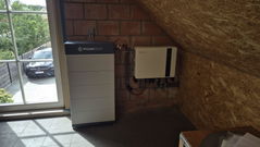
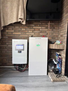
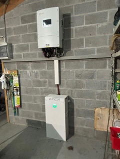
Important to know: Solis hybrid inverters are compatible with leading battery brands. This combination enables applications such as self-consumption optimisation, peak shaving, energy trading via dynamic tariffs and backup power supply during grid outages.

Tip: Not sure which battery best suits your Solis inverter and consumption profile? Use our battery calculator for a personalised recommendation based on your situation.

Practical Installation: Phase Allocation & Smart Metering

Key point: In Solis systems, all single-phase devices must be connected to L1, and the smart meter must be wired completely correctly.

The reason for this is that the inverter internally always uses L1 as the reference phase for power regulation, export limiting and battery control. The smart meter measures all phases (L1, L2, L3), while the inverter controls only one phase actively.

Metering options for Solis hybrid inverters

  • Eastron SDM630MCT (CT meter via RS485): Proven solution for both single-phase and three-phase installations.
  • Xemex P1 meter (wireless via P1 port): Successfully tested on Solis hybrid inverters. Firmware for single-phase inverters is now available. Check current availability of the three-phase firmware with Solis/Rebor before installation.

Common practical scenarios:

  • Single-phase hybrid on a 3-phase grid: Always connect to L1 → otherwise incorrect import/export measurement and faulty battery control occur.
  • 3-phase hybrid + single-phase PV inverter: The single-phase PV inverter must be on L1 → otherwise phase imbalance and incorrect compensation arise.
  • Zero-export systems: Wrong phase = wrong regulation → potential simultaneous import and export.
Common errors Cause Solution
Black meter screen Supply voltage (L + N) not connected Connect supply directly to the meter
Inaccurate energy measurement Wrong neutral reference or CT direction Check N and CT arrow (toward grid)
No communication (MET_Comm_FAIL) RS485 A/B swapped, wrong address or CT fault Check wiring, address (usually 1) and test CTs individually
PV System Architecture & Grid Balancing

The hybrid inverter acts as the central hub between solar panels, battery and the electricity grid. This system manages:

  • Direct use of solar energy
  • Storage of excess energy
  • Peak shaving (reducing peak grid load)
  • Load shifting (moving consumption to cheaper periods)
  • Backup during power outages and grid stability support

How does a hybrid inverter work? (Step-by-step)

  1. Solar panels produce direct current (DC).
  2. The inverter converts DC into alternating current (AC) for the loads.
  3. Excess energy not immediately consumed is stored in the battery.
  4. The battery supplies stored energy during high demand (e.g. in the evening).
  5. If the battery is full and there is no consumption, energy is exported to the grid.

Single-phase vs. three-phase inverters

Single-phase inverters: Compact solutions for smaller residential installations.

Three-phase inverters: Powerful systems for larger homes and commercial applications. These distribute power evenly across multiple phases and are suitable for heavier grid connections.

Troubleshooting Data Logger & Measuring System

Diagnostics for faults:

  • No data in SolisCloud: Check COM port seating, power supply (5V) and ensure a 2.4GHz WiFi network is available.
  • Incorrect values: Check phase connection (L1 mandatory), CT direction (arrow toward grid) and presence of neutral on all points.
  • Black smart meter screen: Check supply voltage (L + N) and consumer unit fuses.
  • Xemex P1 meter no connection: Verify that the correct firmware is installed on the inverter. Firmware for single-phase hybrid inverters is available. Check current availability of the three-phase firmware with Solis/Rebor.
🔧 Diagnosis Protocol: Solis–Eastron MET_Comm_FAIL & RS485 Faults
Key finding from practice: MET_Comm_FAIL is not always caused by a faulty meter or incorrect settings. In a documented real-world case, communication was immediately restored after disconnecting one CT. A CT can deliver plausible readings and still disrupt RS485 communication. CTs must therefore always be actively included in the diagnosis.

Recognisable fault pattern

  • The meter previously communicated correctly with the inverter.
  • Communication suddenly drops — inverter displays MET_Comm_FAIL.
  • The telephone symbol disappears and is replaced by a dot.
  • The Eastron meter display continues to function and shows apparently correct values.
  • Restarting the inverter does not help.
  • Replacing the communication cable brings no improvement.

Step-by-step diagnosis protocol

Step 1 — Document the system precisely
  • Note the exact inverter model (e.g. Solis S6-EH1P6K-L-PLUS).
  • Note the exact meter type and CT specification (e.g. Eastron SDM630MCT, 120A/40mA).
  • Record whether the grid is single-phase or three-phase and which phase the inverter is connected to.
  • Note whether communication has ever worked correctly and when the fault began.

Practical note: When communication has previously worked, the priority shifts from configuration to physical connections, CT-related causes and electronics.

Step 2 — Verify the correct communication port
  • Communication with an external energy meter must run via the RJ45 Meter port — not via the CT-only connection on the 12-pin communication block.
  • Verify that the RJ45 connector is fully clicked into place.
  • Check for couplers, junction terminals or damaged intermediate connectors.
Step 3 — Check basic configuration
  • Energy meter enabled in the inverter settings.
  • Correct meter family selected.
  • Correct grid and phase setting chosen.
  • No recent factory reset or firmware update.
Step 4 — Check RS485 wiring
  • Measure continuity of A and B.
  • Exclude short circuit between A and B.
  • Verify that conductors are correctly seated under the terminal and not clamped on insulation.
  • Check for kinks, tension, pinching and damage at cable glands or conduit entries.
  • Keep RS485 separated from 230/400V cables where possible.
  • RS485 connections on SDM630MCT: terminal 13 (A) and terminal 14 (B).
Step 5 — Measure RS485 voltage

Measure DC voltage between RS485-A and RS485-B using a multimeter:

  • Measure on the meter side between terminals 13 and 14.
  • Measure on the disconnected communication cable toward the inverter.
  • A value between ~1 and 5 VDC may indicate an active RS485 bus.
  • A value of ~0 V may indicate a break, incorrect wiring or a faulty interface.
Step 6 — Test CTs individually ⚠️ Critical step
Safety: A CT secondary circuit must not be left open while primary current is flowing, unless the CT type explicitly permits this. Work de-energised where possible and always follow product and safety instructions.
  • Inspect each CT cable for kinks, crushing, damaged insulation and signs of tension.
  • Disconnect CTs one by one and observe whether communication is restored.
  • Then connect a known good CT.
  • Check whether the telephone symbol returns and MET_Comm_FAIL disappears.
  • Verify that the measurement remains stable afterwards.

Key observation: Communication that is immediately restored after disconnecting one CT is a strong causal indication that the CT or CT wiring is the cause.

Step 7 — Cross-test meter and inverter port
  • Connect a known good meter to the same inverter and cable.
  • If the new meter works immediately → the original meter or CT configuration is suspect.
  • If the new meter also fails → re-examine the inverter port, firmware and cable.
Step 8 — Firmware and Solis support ticket

Only after physical causes have been sufficiently excluded, assess firmware and software. A firmware update may be relevant when the meter and RS485 wiring are demonstrably in order but communication cannot be established reliably. Raise a service ticket with Solis for further support.

Decision matrix

Test result Most likely cause Replace?
0 V on cable toward inverter Cable break or inactive inverter port Not yet
1–5 V on cable, no meter response Meter interface or CT/CT cable Only after cross-test
Communication restored after CT disconnected CT or CT wiring Replace CT, not meter
New meter also fails Inverter port, firmware or cable No meter
New meter works immediately Original meter or CT configuration Possible — after individual test

Internal checklist

  • ☐ Inverter and meter model documented
  • ☐ CT specification verified
  • ☐ Confirmed whether communication previously worked
  • ☐ Correct RJ45 Meter port verified
  • ☐ Meter settings checked
  • ☐ RS485 cable tested for continuity
  • ☐ Voltage A–B measured
  • ☐ CT cables visually inspected
  • ☐ CTs disconnected and tested individually
  • ☐ Known good CT tested
  • ☐ Cross-test with known good meter completed
  • ☐ Firmware and Solis ticket assessed
  • ☐ Return and cost agreements confirmed in writing

This diagnosis protocol is based on a documented real-world case involving a Solis S6-EH1P6K-L-PLUS and an Eastron SDM630MCT (120A/40mA CTs). Safety and manufacturer instructions always take precedence. A single case does not constitute evidence of a structural product defect.

Frequently asked questions about Solis inverters

What is Solis AI and how does it work?

Solis AI is the intelligent energy management system from Solis that automatically responds to dynamic energy tariffs, consumption profiles and weather forecasts — without any manual intervention. The system charges the battery automatically during low energy prices and discharges during high tariffs. Solis AI is compatible with the S6-EH1P (single-phase) and S6-EH3P (three-phase) hybrid inverters. Further information is available in the official Solis AI documentation (EN) or on the Rebor blog page about Solis AI.

Can I use the P1 port of my smart meter as a metering solution for a Solis inverter?

Yes. The Xemex meter has been successfully tested on Solis hybrid inverters with wireless configuration. This allows you to use the P1 port of your smart meter as a metering solution — without separate CT clamps or an external energy meter via RS485. Firmware for single-phase hybrid inverters is available. Please check the current availability of the three-phase firmware with Solis or Rebor before installation. Always verify the most recent firmware version and compatibility list before commissioning.

Why must a single-phase Solis inverter be connected to L1?

Solis uses the L1 phase as a reference point for all internal control algorithms. If connected to L2 or L3, the inverter cannot correctly synchronise energy flows with the smart meter, leading to incorrect measurements and unstable system performance.

Why are the smart meter measurements incorrect?

This is usually caused by a faulty neutral connection, a missing measurement reference, or an incorrect CT direction (the arrow must point towards the grid connection).

What does MET_Comm_FAIL mean on a Solis inverter?

MET_Comm_FAIL means the Solis inverter is not receiving valid communication from the connected energy meter. The cause may lie in the RS485 wiring, meter settings, inverter port, firmware — or, as documented in a real-world case, in a damaged CT or CT wiring. Follow the step-by-step diagnosis protocol above and always include CTs actively in the diagnosis. Do not replace the meter based solely on this error message.

Which home batteries are compatible with Solis hybrid inverters?

Solis hybrid inverters are compatible with leading battery brands including Pylontech, BYD and Dyness. Always verify the current compatibility list and firmware version for your specific inverter model. Calculate which battery suits your situation using our free battery calculator.